Tuesday, March 15, 2011

physics lab number 1 graphs + translations.

Graph 1B (taken from Cindy's group)

1) Start at 1m and stay static for 1s
2) Walk 1.5m in 2s away from the origin, a velocity of 0.75 m/s
3) Stay static at 2.5m for 3s
4) Walk 0.75m in 1.4s towards the origin, a velocity of 0.54m/s
5) Stay static at 1.75m for 2.5s


Graph 1C
1) Start at 3m and walk 1.5m in 3s towards the origin, a velocity of 0.5 m/s
2) Stay static at 1.5m for 1s
3) Walk (faster) 1m in 1s towards the origin, a velocity of 1m/s
4) Stay static at 0.5m for 2s
5) Walk (faster) 2.5m in 3s away from the origin, a velocity of 0.83m/s
 

Graph 1D 

1) Stay static for 2s
2) Walk away from origin at a velocity of 0.5m/s for 3s
3) Stay static for 2s
4) Walk towards the origin at a velocity of 0.5m/s for 3s 


Graph 1E 

1) Increase your speed away from the origin at 0.5m/s in 4s
2) Keep moving away from the origin at 0.5m/s for 2s
3) Move at a constant velocity of 0.4m/s for 3s
4) Stop moving and stay static for 1s


Graph 1F

1) Start at 0.8m and walk 1m in 3.4s away from the origin, a velocity of 0.29m/s
2) Stay static for 3.3s at 1.8m
3) Walk 1.4m in 3.3s away from the origin

Lab result graphs from Timothy. (:

physics lab number 1.

We were given the task in Physics to work with motion detectors and a program called Logger Pro to experiment on motion. This was our first lab for kinematics and although it was pretty challenging it was fun at the same time. It was difficult at first trying to learn how to move in certain ways and at certain times to match the given graph. After a while we got the hang of it and soon we had fun each taking turns to match the graph. The two types of graphs we were told to match were distance/time and velocity/time graphs. The distance/time graphs were easy for me, but understanding how to match the velocity/time graphs was a bit challenging. It was definitely an interesting lab and it was easier to grasp the concepts of these graphs and how to read them but doing them in person instead of just reading a textbook.

Above, is the graph that i walked for the distance/time graphs. The first time i did this graph i was a lot closer at the beginning but sadly, i didn't pay enough attention and walked the wrong way. As well, i learned that the slightest movements during the lab could change the graph by a lot.

Monday, March 7, 2011

Right Hand Rules.

Right Hand Rule #1 (conductor)
Hans Christian Oersted's discovery and and principle that an electric current induces magnetism is represented by a simple rule known as the Right Hand Rule #1.
In this diagram the red line represents the conductor and the blue lines represent the magnetic field. For Right hand rule #1, you use your fingers to represent the magnetic field that is induced by the current (I) and the thumb indicates the direction of the current. If you grasp a conductor with your thumb pointing in the direction of the current, if you claw like a cat, you can find the direction of the magnetic field. If you have either the I or B (magnetic field) you can use the Right Hand Rule #1 in conductors to find the other.


Right Hand Rule #2 (solenoid/electromagnet)
Faraday's principle acknowledges that the change in magnetism will induce a current based on Oersted's discovery. This principle can be explained by using Right Hand Rule #3.


In Right Hand Rule #2, the fingers coil in the direction of the current and the direction that the thumb points is the north pole.
Right Hand Rule #3 (motor)

In Right Hand Rule #3, this rule can be used to explain how motors work. For Right Hand Rule #3, point using your thumb the direction that the current is going in. You release your fingers and point them in the direction of the magnetic field from the north to south pole. Whichever way the palm of your hand points, that is the direction of the force on the conductor placed between the magnets.

Motor Principle

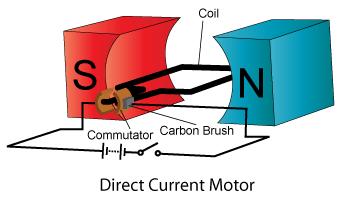
The motor principle is when a conductor carrying a current is found perpendicular to an external magnetic field; the conductor will encounter a force that is perpendicular to the magnetic field it is found in and to itself. We can use the Right Hand Rule #3 to determine the direction of the force that will be applied to the conductor. For Right Hand Rule #3, your fingers point in the direction of the magnetic field, from North to South and the thumb points in the direction of the current. Whichever way the palm of your hand is pointing, is the direction of the force that is exerted of the conductor. For the motor we built, when an electric current is passed through the wires and a magnetic field created by the magnets is present; a force is exerted on the conducting wires causing the cork to rotate 180°. In order for the cork to rotate 360° and make a full turn, you must add commutator pins and brushes. With the addition of these materials, this time when the cork spins half way and the commutator pins come in contact with the brushes, the current is reversed. When you reapply Right Hand Rule #3 to the situation you find out that the force is changed and this change will make the cork spin another 180° making it complete the full turn. 

*Right hand rules determine the direction of conventional current, from positive to negative. If you want to find electron flow, you must use your left hand.

Sunday, February 20, 2011

Electricity.


Ten Important Things About Electricity

1) Difference between a Conventional Current vs. Electron Flow
Conventional current: movement of positive charge flow where the flow travels from the positive terminal to the negative.
Electron Flow: movement of electrons from the negative to positive terminal and the negatively charged electrons are repelling each other.
2) Current
Current is represented by (I) and is the rate of  charge flow and is measured in Amperes (A). 
It is calculated by dividing Charge (Q) by Time (t) in seconds. ---> I= Q/t
Charge is represented by Q and is the total amount of charge moving past a point in a conductor and is measured in Coulombs (C).

3) Voltage
Voltage is represented by (V) and it is the electric potential energy for each coulomb of charge in a circuit. Another name for Voltage is electric potential difference. It is measured in volts (V). 
It is calculated by dividing Energy (E) by Charge (Q). ---> V= E/Q or V= W/Q
(E) is energy required to increase the electric potential of a charge and it is measured in Joules.

4) Energy
The energy delievered to a load depends on the potential energy by charge and the rate of the charge that is being delivered (current).
Energy transferred by charge flow is calculated by : E= VIt (Voltage*Current*time)

5) Measurement using a Anmeter and Voltmeter
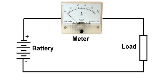
An anmeter is a device that measures current (I) and it must be wired so that all current flows through it. This anmeter should be a exceptional conductor so that no energy is lost. It must be wired in Series with the Circuit.
A voltmeter is a device that measures Voltage (V)which is the potential difference between any two points. The voltmeter, unlike the anmeter should be a poor conductor and have a high resistance so that it is less than the load it is connected to so that the measurement by the voltmeter directs less of a current from the circuit it is connected to. The Voltmeter must be connected in parallel with the load (before and after).
6) Ohm's Law
The measurement of the opposition of flow is called resistance. Resistance is represented by (R) and is measured in Ohms. It is the relationship that connects Current, Voltage, Resistance, and Power. It can be calculated according to a pyramid chart.
where R= V/I, V= IR, I= V/R

7) Kirchhoff's Law
*This law applies to both series and parallel circuits.
i. Current Law states that the total current flowing into a connection equals total current flowing out a connection.

ii. Voltage Law states that the algebraic sum of the potential differences around a closed pathway equal zero.

8) Series and Parallel Circuits
In a Series Circuit, charge flows along one path. The equations for a series circuit are:
I total = I1=I2=I3=...In
V total = V1+V2+V3+...Vn
R total = R1+R2+R3+...Rn

In a Parallel Circuit, charge flow along two or more paths. The equations for a parallel circuit are:
I total = I1+I2+I3+...In
V total = V2=V2=V3=...Vn
1/R total = 1/R1+ 1/R2+ 1/R3+ ...1/Rn

9) Power ( watts)
P=IV , P=V2R, P=I2R
Cost: P (in kW). t(hours). cost rate

10) Energy ( joules)
E=VIt


Sunday, February 13, 2011

Ohm's and Kirkenoff's Law

Ohm's Law

This law explains the relationships between Resistance (R), Current (I), Power (P), Voltage (V).
Resistance (R) is measured in Ohms. Resistance along a conductor depends on 4 things, length, cross-sectional area, the material is is made of, and it's temperature.
It states that in a conductor, the direct current (I) that flows between its ends are proportional to the potential difference (V). The amount of voltage (potential difference) and the current are proportional as long as certain variables are controlled, such as temperature. For a certain voltage, is there is a higher resistance, there will be a lower current flow.
A formula that is used for Ohm's is: Resistance (R) = Voltage (V)/Current (I)
There is 1 ohm of resistance when 1 ampere of current that has 1 voltage flows through a resistor.
With this triangle, you can simply find the formula you need.

Kirchoff's' Laws

Kirchoff''s current law (textbook) : The total amount of current into a junction point of a circuit equals the total current that flows out of that same junction.


Kirchoff''s voltage law (textbook) : The total of all electrical potential decreases in any complete circuit loop is equal to any potential increases in that circuit loop.
The total voltage lost through the circuit is equal to the original total voltage.

For a Series Circuit:
IT= I1= I2= I3= I4=...IN
VT= V1 +V2+V3+ V4+...VN
RT= R1+R2+R3+R4+...RN

For a Parallel Circuit:
IT= IT+I1+I2+I3+I4+...IN
VT= V1= V2= V3= V4=...VN
RT= 1/R1+ 1/R2 + 1/R3+ 1/R4+...1/RN

Wednesday, February 9, 2011

My Favourite Roller Coaster Design.

This summer, I managed to conquer my fear of heights... well sort of.

When I was younger I thought that I was so brave because I went on Taxi Jam at Wonderland, but as I got older, I realized that it was not a roller coaster, but a kid's ride. The actual roller coasters were much higher and much scarier. Having a fear of heights, I tried my best to stay away from roller coasters.


Not until this year, did I get a season's pass and go on most of the rides at Wonderland.  My greatest fear was Behemoth. Often when we drove past Wonderland on the highway I would see Behemoth, its eye-catching colours and the track with the incredibly high drop.


 On my second trip to Wonderland, I managed to half force myself onto the ride. I say half force because in a way I was curious just how scary the ride could be. It was dark already so on the ride I really couldn't see anything at all. The second time I rode Behemoth, I had my eyes wide open because I wanted to see everything. The worst and best part of the design would be the first drop. Another thing I love about the design of Behemoth are the multiple drops and the amazing height. The large curve is also another reason why this design is my favourite. At night, there are lights along the ride makes it nice as well. One of my friends told the reason why the seats are positioned the way they are is so that everyone on the ride can have a good view of everything during the ride. Basically... I love the design of this roller coaster. (:

Monday, February 7, 2011

The Energy Transformation from a Battery to a Circuit

Electron Flow

In a simple circuit, you will find a battery (power supply), wires (conductor), and a light bulb (load).  . Normally, on the battery you will find the positive terminal on top and negative on the bottom. Wire that is attached the positive terminal is attached the the bottom of the light bulb and wire attached to the negative terminal is attached the side. With these wires connected to the battery, this creates a circuit.

Chemical energy is stored in a battery, and when this battery is attached to a circuit, the chemicals within it react. This process happens only when there is a circuit and when the electrons begin to flow. The charged electrons start out from the negative terminal and flow into the wire towards the light bulb and out because they are attracted to the positive terminal. A current is produced as the electrons make their way through the circuit.

The continuous flow of electrons into the light bulb cause it to produce light and heat. On the way to the positive terminal the electrons lose electric voltage. Once the electrons not as charged as they once were complete the circuit and reach the positive terminal they are once again recharged. The electrons travel back to the negative terminal where their electric potential and goes back to how it was normally. The electrons will  then complete the circuit again and again in the same process.

http://www.energyquest.ca.gov/story/chapter05.html