Our next challenge in physics is to build an egg glider. Our initial ideas were we had to build a basket of some sort to protect the egg because not only does our egg glider have to glide, when it lands, the egg can not have any cracks. This was the hard part because we're only given four different types of materials, a table length of tape, 25 straws, scissors and a sheet of newspaper. Different ideas were brought up as the wider the area, the more force is spread and the force won't be concentrated on the egg, causing it to break. Although this was a good idea, it was hard to achieve because not only did we have to build the protection for the egg, we needed to build wings for the glider.
For the wings we decided if we made them bigger it would be better, but Mr.Chung warned us if we made our wings too big, it would easily get damaged. A lot of our glider sketches in my opinion looked like a kite.
We drew rough sketches of different combinations and we decided we would build a large wing and in the center, we would attach the egg "basket" containing the egg. For the basket, we would either make a chamber cutting the straws in half the using them to make the sheet and wrap it or make a cone shape.
It was very difficult to come up with ideas because of the limit of materials. We couldn't use too many straws on either the basket or the glider. So at the end of the class we had a rough sketch of what we wanted to build but we weren't sure if it would be possible to build.
Our egg glider sort of resembled an airplane so when searching up aerodynamics i used this website for a basic understanding of how airplanes work:
http://science.howstuffworks.com/transport/flight/modern/airplane1.htm
what i realized was this is actually really difficult because lift=weight and drag=thrust. This means the the top and bottom area of the plane and front and back must be equal to keep up the plane. If we incorporated that idea into our plane, it would be really difficult because the egg would definitely be heavier than the glider structure making it unbalanced.
To get an overall understanding of simple aerodynamics and how it works in a car:
http://www.howstuffworks.com/fuel-efficiency/fuel-economy/aerodynamics.htm
I learned about air resistance: forces acted upon a moving object by the far, also known as drag
and the idea of how air and wind are kind of like a wall on a really windy day and you're trying to move through it at a high speed. Although we weren't building it based on a car and it moving at high speeds, it was interesting to learn about that.
Thursday, March 31, 2011
Saturday, March 26, 2011


Tuesday, March 15, 2011
physics lab number 1 graphs + translations.
Graph 1B (taken from Cindy's group)
1) Start at 1m and stay static for 1s
2) Walk 1.5m in 2s away from the origin, a velocity of 0.75 m/s
3) Stay static at 2.5m for 3s
4) Walk 0.75m in 1.4s towards the origin, a velocity of 0.54m/s
5) Stay static at 1.75m for 2.5s


Graph 1C
1) Start at 3m and walk 1.5m in 3s towards the origin, a velocity of 0.5 m/s
2) Stay static at 1.5m for 1s
3) Walk (faster) 1m in 1s towards the origin, a velocity of 1m/s
4) Stay static at 0.5m for 2s
5) Walk (faster) 2.5m in 3s away from the origin, a velocity of 0.83m/s


Graph 1D
1) Stay static for 2s
2) Walk away from origin at a velocity of 0.5m/s for 3s
3) Stay static for 2s
4) Walk towards the origin at a velocity of 0.5m/s for 3s


Graph 1E
1) Increase your speed away from the origin at 0.5m/s in 4s
2) Keep moving away from the origin at 0.5m/s for 2s
3) Move at a constant velocity of 0.4m/s for 3s
4) Stop moving and stay static for 1s


Graph 1F
1) Start at 0.8m and walk 1m in 3.4s away from the origin, a velocity of 0.29m/s
2) Stay static for 3.3s at 1.8m
3) Walk 1.4m in 3.3s away from the origin


Lab result graphs from Timothy. (:
physics lab number 1.
We were given the task in Physics to work with motion detectors and a program called Logger Pro to experiment on motion. This was our first lab for kinematics and although it was pretty challenging it was fun at the same time. It was difficult at first trying to learn how to move in certain ways and at certain times to match the given graph. After a while we got the hang of it and soon we had fun each taking turns to match the graph. The two types of graphs we were told to match were distance/time and velocity/time graphs. The distance/time graphs were easy for me, but understanding how to match the velocity/time graphs was a bit challenging. It was definitely an interesting lab and it was easier to grasp the concepts of these graphs and how to read them but doing them in person instead of just reading a textbook.
 Above, is the graph that i walked for the distance/time graphs. The first time i did this graph i was a lot closer at the beginning but sadly, i didn't pay enough attention and walked the wrong way. As well, i learned that the slightest movements during the lab could change the graph by a lot.

Monday, March 7, 2011
Right Hand Rules.
Right Hand Rule #1 (conductor)
Hans Christian Oersted's discovery and and principle that an electric current induces magnetism is represented by a simple rule known as the Right Hand Rule #1.
 In this diagram the red line represents the conductor and the blue lines represent the magnetic field. For Right hand rule #1, you use your fingers to represent the magnetic field that is induced by the current (I) and the thumb indicates the direction of the current. If you grasp a conductor with your thumb pointing in the direction of the current, if you claw like a cat, you can find the direction of the magnetic field. If you have either the I or B (magnetic field) you can use the Right Hand Rule #1 in conductors to find the other.
Right Hand Rule #2 (solenoid/electromagnet)
Faraday's principle acknowledges that the change in magnetism will induce a current based on Oersted's discovery. This principle can be explained by using Right Hand Rule #3.

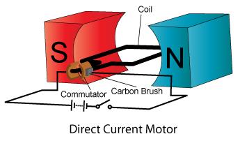
 In Right Hand Rule #3, this rule can be used to explain how motors work. For Right Hand Rule #3, point using your thumb the direction that the current is going in. You release your fingers and point them in the direction of the magnetic field from the north to south pole. Whichever way the palm of your hand points, that is the direction of the force on the conductor placed between the magnets.
Motor Principle

*Right hand rules determine the direction of conventional current, from positive to negative. If you want to find electron flow, you must use your left hand.
Hans Christian Oersted's discovery and and principle that an electric current induces magnetism is represented by a simple rule known as the Right Hand Rule #1.

Right Hand Rule #2 (solenoid/electromagnet)
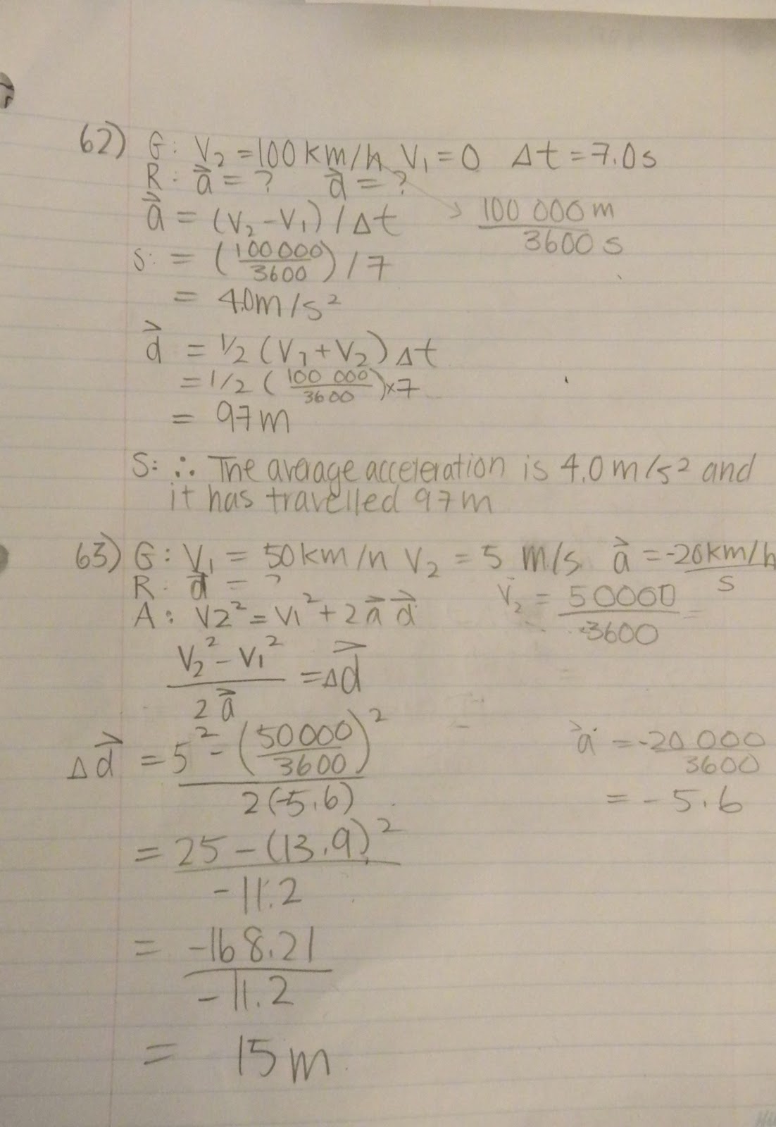
Faraday's principle acknowledges that the change in magnetism will induce a current based on Oersted's discovery. This principle can be explained by using Right Hand Rule #3.

In Right Hand Rule #2, the fingers coil in the direction of the current and the direction that the thumb points is the north pole.
Right Hand Rule #3 (motor)Motor Principle
The motor principle is when a conductor carrying a current is found perpendicular to an external magnetic field; the conductor will encounter a force that is perpendicular to the magnetic field it is found in and to itself. We can use the Right Hand Rule #3 to determine the direction of the force that will be applied to the conductor. For Right Hand Rule #3, your fingers point in the direction of the magnetic field, from North to South and the thumb points in the direction of the current. Whichever way the palm of your hand is pointing, is the direction of the force that is exerted of the conductor. For the motor we built, when an electric current is passed through the wires and a magnetic field created by the magnets is present; a force is exerted on the conducting wires causing the cork to rotate 180°. In order for the cork to rotate 360° and make a full turn, you must add commutator pins and brushes. With the addition of these materials, this time when the cork spins half way and the commutator pins come in contact with the brushes, the current is reversed. When you reapply Right Hand Rule #3 to the situation you find out that the force is changed and this change will make the cork spin another 180° making it complete the full turn.
Subscribe to:
Comments (Atom)